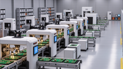
Top 10 Types of PCB Design Global Buyers Need to Know
Global buyers rarely purchase a bare circuit board. They purchase predictable performance, manufacturability, traceability, and support. That is why understanding the major types of PCB design matters before comparing suppliers, quotations, or production locations.
This guide, “Top 10 Types of PCB Design Global Buyers Need to Know,” examines practical categories such as single-sided, multilayer, HDI, rigid-flex, flexible, metal-core, RF, and high-speed boards. Each type solves a different engineering problem. A multilayer board may control impedance and reduce noise. A metal-core board may move heat away from high-power LEDs. A rigid-flex design may save space inside a medical instrument, but it can increase material and assembly complexity.
Details matter.
EMC engineer Henry Ott famously advised, “The best way to solve an EMC problem is to avoid having it in the first place.” His principle remains valuable in modern PCB design. Stackup planning, return-path control, grounding, thermal analysis, and component placement should begin before routing starts. Buyers should also review DFM feedback, controlled-impedance reports, material specifications, inspection records, and test coverage.
There is no perfect ranking. Some categories overlap, and a board can combine several technologies. That is where judgment becomes important. A low-cost prototype may not suit volume production. A technically advanced design may create unnecessary sourcing risks. This overview offers a practical starting point, while encouraging buyers to question assumptions, verify supplier capability, and match each PCB design to its application, environment, and expected service life.
How PCB Designs Are Classified for Global Purchasing Decisions
Top 10 Types of PCB Design Global Buyers Need to Know
How PCB Designs Are Classified for Global Purchasing Decisions
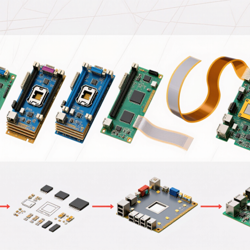
Global buyers classify PCBs by structure, materials, density, and operating environment. The main types include single-sided, double-sided, multilayer, rigid, flexible, rigid-flex, HDI, metal-core, high-frequency, and embedded-component boards. Each category changes tooling, inspection, packaging, and delivery risk. A four-layer rigid board may suit industrial controls, while a flexible circuit fits a hinged medical device. The decision is rarely about layer count alone.
IPC industry data shows that electronics supply chains continue shifting toward higher-density interconnects and stronger quality controls. WSTS reported global semiconductor sales of 627.6 billion US dollars in 2024. That growth increases demand for compact, reliable PCB assemblies. HDI designs need precise laser drilling and tighter registration. High-frequency boards require controlled impedance and carefully selected dielectric materials. Buyers should request stack-up drawings, impedance reports, material certificates, and cross-section samples before approving production.
In supplier audits, I have found that “multilayer” can hide major differences. One supplier may quote standard FR-4, while another assumes low-loss laminate. The prices look comparable. They are not.
Flex and rigid-flex designs also need bend-radius data, copper-thickness limits, and dynamic-cycle testing. UL and IPC requirements can support purchasing confidence, but certificates alone cannot prove process stability. Mistakes still happen. A clear specification, traceable inspection records, and a small pilot order often reveal problems before volume production.
Rigid, Flexible, and Rigid-Flex PCB Design Types
Rigid, flexible, and rigid-flex boards solve different mechanical and electrical problems. Rigid PCBs suit stable assemblies, such as control panels, sensors, and industrial equipment. Their solid glass-reinforced structure supports dense components and repeatable production. However, rigid does not mean simple. Layer count, copper weight, thermal paths, and impedance still require careful control.
Flexible PCBs bend around hinges, narrow spaces, and moving parts. Their polyimide structure can reduce connectors, wiring, and assembly weight. Designers must define bend radius, flex zones, stiffeners, and copper grain direction early. Repeated bending needs more than a visual check. Rigid-flex PCBs combine stable mounting areas with flexible connections. They can improve reliability by removing cable assemblies, but their transitions demand precise stackup planning. I once underestimated that transition area; the layout looked clean, yet the mechanical clearance failed during testing. That mistake was avoidable.
Tips: Ask the fabricator for material limits before routing. Mark static and dynamic bend regions clearly. Keep vias and components away from active flex zones. Confirm bend radius with the actual enclosure, not only a CAD model. Request cross-section review, dimensional inspection, and electrical testing before volume production. Check applicable industry standards and regional requirements with qualified engineers. A cheaper rigid-flex design can become expensive after rework. Also, leave room for uncertainty. Real assemblies flex differently than simulations suggest.
Single-Layer, Double-Layer, and Multilayer PCB Designs
Among the top ten PCB design types, single-layer, double-layer, and multilayer boards remain essential for global buyers. A single-layer PCB places copper traces on one side only. It suits LED lighting, simple sensors, and basic control panels. Production is usually economical, and inspection is straightforward. However, routing becomes difficult when components increase. Long traces may also create unwanted electrical noise.
Double-layer PCBs use copper on both sides, connected through drilled vias. This structure supports denser layouts, compact power supplies, and industrial monitoring equipment. During sourcing, buyers should check hole accuracy, copper thickness, and solder-mask quality. A low-cost board can look acceptable but fail after repeated temperature changes. That detail is easy to miss.
Multilayer PCBs contain several copper layers separated by insulating material. Four-layer designs commonly improve routing space and signal control. More advanced boards may use six, eight, or even more layers for computing, medical instruments, and communication equipment. Designers can place power and ground planes inside the board, reducing loop areas and interference. Yet extra layers increase pressing complexity, testing requirements, and delivery risk. In my experience reviewing fabrication data, unclear layer-stack drawings cause avoidable delays. Buyers should request impedance information, material specifications, tolerance tables, and test records before approval. Still, specifications alone cannot predict every field problem. Assembly conditions, humidity, thermal cycling, and actual operator handling also matter.
High-Density, High-Frequency, and Metal-Core PCB Designs
Top 10 Types of PCB Design Global Buyers Need to Know
High-density interconnect, high-frequency, and metal-core boards now serve demanding applications. IPC’s 2024 industry survey reported continuing pressure for smaller, faster, and more reliable electronics. That pressure changes purchasing decisions. HDI boards use microvias, fine lines, and sequential buildup. They fit more functions into compact medical, automotive, and communication devices. Buyers should request controlled impedance data, via reliability results, and cross-section samples. Density alone proves little.
High-frequency designs require careful material selection and disciplined geometry. Signal loss, dielectric variation, copper roughness, and connector transitions can affect performance above several gigahertz. The World Semiconductor Trade Statistics forecast renewed semiconductor growth for 2024, increasing demand for high-speed control and communication hardware. Yet faster chips do not automatically create better boards. Trace length still matters. So does grounding.
Metal-core PCBs manage heat through aluminum or copper substrates. They suit LED systems, power modules, and compact converters where thermal paths are short. Industry market analyses have placed the global PCB market above 70 billion US dollars in recent years, with advanced substrates gaining share. Buyers should compare thermal resistance, dielectric thickness, solder-mask durability, and warpage limits. Ask for test conditions, not only headline values.
A practical mistake is treating all three designs as interchangeable. They are not. One prototype may pass electrical tests but fail after thermal cycling. That deserves attention. Specifications should include operating temperature, impedance tolerance, copper weight, surface finish, and inspection standards. Independent laboratory verification improves confidence, although it adds time and cost. เครดิตฟรี
Top 10 Types of PCB Design Global Buyers Need to Know - High-Density, High-Frequency, and Metal-Core PCB Designs
| No. | PCB Design Type | Typical Construction | Main Characteristics | Common Applications | Key Buyer Considerations | Relevant Standards |
|---|---|---|---|---|---|---|
| 1 | HDI PCB | Microvias, fine traces, sequential lamination, and high routing density; commonly built with one or more sequentially laminated layers. | More interconnections in a smaller area, reduced via size, shorter signal paths, and improved component escape routing. | Smartphones, compact computing devices, medical electronics, cameras, and advanced control modules. | Microvia reliability, laser-drilling capability, registration accuracy, impedance control, inspection coverage, and yield at fine geometries. | IPC-2221, IPC-2226, IPC-6016 |
| 2 | High-Frequency / RF PCB | Low-loss dielectric materials, controlled trace geometry, solid reference planes, and RF-specific stack-up design. | Designed for high-frequency signal integrity, stable dielectric performance, low insertion loss, and controlled impedance. | Radar, wireless infrastructure, satellite communications, antennas, navigation systems, and test equipment. | Dk and Df tolerance, copper roughness, material availability, RF simulation, via transitions, and manufacturing consistency. | IPC-2221, IPC-4103, IPC-6018 |
| 3 | Metal-Core PCB | A metal base, usually aluminum or copper, combined with a dielectric layer and one or more copper circuit layers. | Improved heat spreading, reduced thermal resistance, and better mechanical support than standard resin-based boards. | LED lighting, power converters, automotive electronics, motor controls, and thermal management modules. | Thermal conductivity, dielectric breakdown voltage, flatness, isolation thickness, thermal expansion, and machining requirements. | IPC-2221, IPC-4101, IPC-6012 |
| 4 | Flexible PCB | Flexible copper-clad laminate with polyimide or similar flexible dielectric; may include coverlay and stiffeners. | Bends, folds, and conforms to three-dimensional packaging while reducing wire harnesses and interconnect weight. | Wearables, cameras, displays, medical instruments, automotive sensors, and compact consumer devices. | Minimum bend radius, dynamic versus static flexing, copper grain direction, coverlay design, crease control, and connector durability. | IPC-2223, IPC-6013 |
| 5 | Rigid-Flex PCB | Rigid multilayer sections connected by flexible circuit sections within one integrated board assembly. | Combines structural support with three-dimensional routing, reducing connectors, cables, and assembly points. | Aerospace systems, medical equipment, industrial controls, robotics, and high-reliability electronics. | Bend-zone design, rigid-to-flex transitions, layer registration, thermal stress, fabrication drawings, and assembly handling. | IPC-2223, IPC-6013, IPC-6018 |
| 6 | High-Speed Digital PCB | Multilayer construction with dedicated power and ground planes, controlled-impedance routing, and signal-integrity features. | Supports fast edge rates and high data throughput while controlling reflections, crosstalk, skew, and power noise. | Servers, network equipment, storage systems, industrial computing, instrumentation, and embedded processors. | Stack-up modeling, differential-pair geometry, length matching, return paths, via stubs, power integrity, and fabrication tolerances. | IPC-2221, IPC-2141, IPC-6012 |
| 7 | Multilayer PCB | Three or more conductive layers separated by dielectric material and laminated into a single board structure. | Provides higher routing capacity, power-plane integration, better electromagnetic control, and compact packaging. | Industrial automation, telecommunications, medical electronics, automotive systems, and computing hardware. | Layer count, lamination cycle, board thickness, dielectric spacing, warpage, sequential drilling, and impedance requirements. | IPC-2221, IPC-6012, IPC-4101 |
| 8 | Heavy-Copper PCB | Circuit layers using copper thicknesses above standard production values, often with plated-up traces or mixed copper weights. | Carries high current, withstands thermal cycling, and provides improved electrical and mechanical robustness. | Power distribution, battery systems, renewable-energy equipment, industrial drives, and automotive power electronics. | Copper weight, etching compensation, plating uniformity, thermal relief, current capacity, drill wear, and solderability. | IPC-2221, IPC-2152, IPC-6012 |
| 9 | Ceramic PCB | Ceramic substrate materials such as alumina or aluminum nitride with thick-film, thin-film, or direct-bonded copper structures. | High thermal conductivity, strong dimensional stability, low moisture absorption, and suitability for demanding temperatures. | Power modules, high-brightness lighting, RF modules, laser equipment, sensors, and high-temperature electronics. | Ceramic grade, thermal expansion matching, metallization method, brittleness, surface finish, flatness, and specialized processing cost. | IPC-2221, IPC-6012, applicable ceramic substrate specifications |
| 10 | Backplane PCB | Large, mechanically rigid multilayer board with extensive connectors, power distribution, and high-density signal routing. | Interconnects multiple plug-in boards or modules and may support high-speed serial links and substantial power loads. | Telecommunications platforms, servers, storage systems, industrial control racks, and transportation electronics. | Board size, mechanical rigidity, connector alignment, high-speed channel loss, controlled impedance, insertion cycles, and test access. | IPC-2221, IPC-6012, IPC-4101 |
How to Match Each PCB Design Type to Its Application and Requirements
Top 10 Types of PCB Design Global Buyers Need to Know
Choosing a PCB design begins with the application, not the supplier’s catalogue. Prismark reported global PCB sales near US$69 billion in 2023, showing the scale of this market. Yet market estimates vary, so buyers should verify every forecast and specification.
A single-sided board suits simple controls and low-cost products. Double-sided boards support denser wiring without major cost increases. Multilayer boards fit computers, industrial controllers, and complex power systems. Rigid boards offer stable mechanical support. Flex boards bend inside cameras, medical wearables, and compact sensors. Rigid-flex designs reduce connectors in moving assemblies. HDI designs serve smartphones and miniature devices with fine traces and microvias.
The application decides the rest. Metal-core PCBs move heat away from LEDs and power modules. Ceramic PCBs handle high temperature, insulation, and demanding RF conditions. RF and microwave designs require controlled impedance, low-loss materials, and careful connector placement.
IPC-2221 design guidance remains a useful foundation, but it cannot replace thermal testing or production feedback. Mordor Intelligence forecasts continued PCB market growth through the decade, driven by vehicles, communications, and automation. That growth may encourage rushed decisions. Do not confuse a higher layer count with better engineering.
Tips: Share voltage, current, frequency, bend radius, operating temperature, and annual quantity early. Request impedance coupons and cross-section reports. A prototype can expose hidden noise, warpage, or heat problems. Leave space for inspection. Perfect drawings still fail in real assemblies.
Related Posts
-
Top PCB Printing Manufacturers for Global Buyers
-
Innovative Trends in PCB Printing That Will Transform the Electronics Industry
-
How to Create a PCB Prototype for Your Electronics Project?
-

Best PCB Prototype Solutions for Global Buyers Today?
-
The Future of Printed Circuit Boards: Innovations Shaping Our Electronic Devices
-
What is PCB Board Design and Why is it Important for Exporters?